Broadcast Audio Testing with dScope Series III
Linked Resources:
New technology brings new challenges with it, and the
move to digital and software-based equipment means that
engineers and systems installers have had to evolve new,
reliable means of testing their equipment. Graham Boswell,
co-founder of audio and test and measurement
manufacturers Prism Sound, details some best-practice
test and measurement routines, and explains how they can
be adapted for practical, everyday use.
| APPLICATION NOTES |
| PRESENTATIONS |
| QUICK STARTS |
| WEBINARS |
| RELEVANT PRODUCTS |
The introduction of digital audio storage and transmission in the broadcast industry has brought with it new opportunities and new problems, including changes to the way equipment is tested - headphones are no longer sufficient on their own! Extensive best practice routines have been suggested by manufacturers and standards bodies, but these are usually more detailed than the average broadcast engineer or systems installer needs them to be. With a little thought, however, these procedures can be adapted and turned to practical use.
The Audio Engineering Society (AES) and the European Broadcasting Union (EBU) championed the AES/EBU interface. Now better known as AES3-2003, the standard also forms part of IEC 60958.
AES17 recommends methods for testing digital audio equipment. Surprisingly, although most seem to be aware of AES3, it appears that few know of AES17. A personal copy can be obtained from www.aes.org, and a useful one-sheet summary is available at www.prismsound.com/AES17.
Readers will soon realise that to implement all of the tests outlined in AES17 will be time-consuming. Many engineers rely on a smaller sub-set of measurements, typically including frequency response and distortion and various others. For systems that are business-critical, this can be a risk.
More on AES17
AES17 aims to provide a consistent methodology for manufacturers and system builders. Instead of stating all of the test conditions and settings, it is convenient to state 'measured in accordance with AES17'. AES17 covers A-A, A-D, D-D and D-A modes. There are several common considerations: input characteristics, output characteristics, linear response, amplitude non-linearity, signal-to-noise ratio and crosstalk and channel separation.
When using AES17, it is not always necessary to perform all of the tests. It is reasonable to select a relevant and useful sub-set to prove basic performance, for example.
Test Equipment
It is advisable to obtain a good digital audio test system. A search for "digital audio analyzer" in Google or Live.com will produce a good selection. When choosing test equipment, it is worth considering not only the measurement capability, but also whether testing can be automated. Automation provides many benefits: consistency, ease of use, ease of documentation, and speed, to name but a few. Prism Sound offer AES17-compliant automation scripts.
Alternatively, those with existing analogue equipment might prefer a digital-only test set, and there are several of these on the market. Particularly important is the need to test the performance of digital equipment ports providing an AES3 or AES11 interface. The key differentiator is the ability not only to measure interface jitter, but to be able to separate the Fs-jitter (sampling-rate jitter, source-related) and data-jitter (data-rate jitter, cable-related) components. There are several portable Digital Interface Analyzers on the market and again, automation and programmability pay dividends in consistency, ease of use and speed. Using the Internet "AES3 Interface Analyzer" is a good search string.
Pragmatic digital signal path & codec tests
One of the key differences between analogue and digital audio transmission is the need to characterise the digital audio carrier (or bearer) signal separately from the audio content. Unlike analogue systems, digital transmission systems do not degrade the audio gracefully or progressively. As the carrier becomes progressively degraded, audio transmission will suddenly fail. Symptoms are sometimes heard as pops and glitches or dropouts in the audio. Depending on error concealment on the playback equipment, the corrupted audio may simply sound distorted or have periodic mutes. Intermittent audio or audio with clicks, ticks, glitches and pops is usually a sign of a degraded digital carrier or clock synchronization issues. A degraded signal may be received correctly most of the time, but "tick" infuriatingly at irregular and infrequent intervals or even have intermittent errors in the metadata.
The simplest way to test a transparent digital signal path is to send a known data pattern and to check that it is received correctly without any bit errors. Surprisingly, some mainstream digital audio test equipment is not capable of performing this test, so it is a good idea to check that it is supported if buying a system equipped for testing AES3 or S/PDIF interfaces. On the dScope Series III and DSA-1 digital audio analyzers, this test is called "Channel Check" and can be performed at 16, 20 or 24 bit word lengths. The sequence can also be recorded and replayed to check digital recording integrity, and can be played through a digital channel to a remote analyzer to check transmission integrity. The receiving analyzer can also keep a log of channel failures over time to verify the long term reliability of the channel. On the dScope Series III this is achieved using the "Event Manager" to log channel check failure events.
There is no error detection or correction for audio embodied in the AES3 format and measurement of bit-error-rate (BER) is somewhat academic. However, to prove reliability a check for error-free operation may be performed over a period of time. This might be several minutes, an hour or 24 hours. In any case, the required result is zero errors. Ideally, the software will log errors to a file and also indicate errors to the user as they are detected. For a non-transparent path, such as those including data reduction codecs, A/D or D/A converters, different techniques must be used. For linear audio performance tests, there are the 'traditional' frequency response, noise and distortion tests, or for quicker testing, Multi-tone or Farina techniques can be used. However, these are less likely to be useful in determining the reliability of the audio path over time and freedom from clicks or drop-outs.
A test that we commonly use at Prism Sound is to transmit a high-quality sine wave and to measure distortion over time using a tight maximum reading limit. Breaches of the reading limit are logged against time. This is not a perfect method, but is useful. Again, the required result is zero errors. There are several problems with this technique, but space prevents me from elaborating further.
Testing of data reduction codecs is a subject in its own right, but suffice to say here that we should take care to distinguish in our results between coding artefacts and A/D or D/A converter or signal processing performance issues.
Most popular data reduction codecs today (MP3 or APT-X, for example) use 'perceptual coding', by means of which chunks of data are removed until the loss of information becomes noticeable or at worst, objectionable.
We can use multi-tone test signals to place stimulus components in each of the critical bands of the codec, thus forcing it to work harder. We can then usually see the Codec noise in the spectrogram produced by a Fast-Fourier-Transform (FFT) analyzer. This could cause confusion for the unwary expecting to see the low noise levels associated with today's 24-bit A/D and D/A converters.
Variable bit-rate codecs (such as Microsoft's WMA or Ogg Vorbis) can increase the bit-rate in response to a more complex signal, instead of compromising quality, so it is important to know the type in use before attempting any assessment of channel performance.
Testing Digital Audio Interfaces
Tests of digital audio interfaces can be broken down into tests of transmitters, receivers and tests within installations where significant cable runs are included. It is desirable to be able to perform these tests in conjunction with the integrity checks mentioned above - for example, we may wish to check a path incorporating a long run and to see that the receiving device is error free with a degraded carrier.
Digital Audio Interface Tests
Measurements for digital interfaces can include:
Measurements for digital interfaces can include:
FOR AES3 TRANSMITTERS (WITH OR WITHOUT LONG
CABLES)
|
FOR AES3 RECEIVERS (LONG CABLES WILL BE
SIMULATED)
|

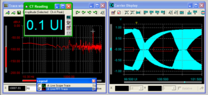
Figure 1: Example eye pattern measurement
click the graphic for a larger view (opens in new window)
We may also check for meta-data implementation such as Channel Status, as well as checking the number of bits used in the audio data field and synchronization with a house clock. Suggested measurements for AES3 transmitters and receivers are given in Box 1.
The Quick Check
Sometimes a quick "go/no go" test is needed for a mixed analogue & digital channel. One of the best ways to achieve this is to use a multi-tone test.
Quick Signal Checks
One of the best ways to implement a quick "go/no go" test is to use a multi-tone
It can be difficult to relate some of the results obtained from
multi-tone tests to the standard results such as THD+N and Noise
and so it is not uncommon for a 'golden system' to be tested
conventionally and then again using multi-tones so that a
reference result can be established.
One of the best ways to implement a quick "go/no go" test is to use a multi-tone

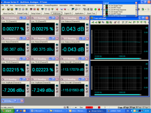
Figure 2: Example multi-tone measurement
click for a larger view
Limits can then be set and a channel measurement including various results such as frequency response, amplitude sensitivity, minimum headroom, distortion and noise and crosstalk can be made in less than a second. Where there are many lines to check this can be a real advantage, especially if combined with automated routing for the paths to be tested.
The screenshot shown here [Figure 2] shows a sample display for a multi-tone test. The results were obtained in about half a second.
Conclusions
In today's digital broadcasting world, there is more equipment to test, and many more ways of testing it. Fortunately, the agile-minded engineer can develop ways to limit what needs to be done to the essentials, and expedite these procedures with highly integrated automated equipment. New techniques like multi-tone testing can vastly reduce testing time and new test problems arising from the adoption of new technology can be addressed with specialist equipment.
Further Resources
For further details of testing with dScope Series III, consult the dScope on-line help or download the dScope operation manual. For any more information or assistance please contact us using the form below:
App ID: 0015, Resource ID: 84

