Test and Measurement Technical Data
dScope inputs and outputs: balanced/unbalanced operation and grounding
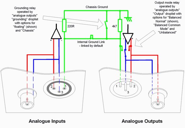
When driving an unbalanced EUT input, the dScope’s analogue output should be set to ‘unbalanced’ mode. In this mode, the outer conductor (shield) of the BNC coax connector and pin 3 of the XLR connector are connected to signal ground (0V) of the generator. Pin 1 of the XLR connector is permanently connected to signal ground in all modes. Refer to the diagram below:
When analyzing an unbalanced EUT output, the dScope analyzer input offers some different grounding options so that you can select the best one for your particular test conditions in order to avoid hum problems.
To avoid ground loops, which can induce hum in any sensitive system, the input of the dScope analyzer is electronically balanced (differential) so that it can operate without an internal ground reference. Signal ‘hot’ is on XLR pin 2 and BNC inner and signal ‘cold’ is on XLR pin 3 and BNC outer (shield). Note that, unless you ground it yourself, the input BNC outer (shield) is not grounded, but is simply the ‘cold’ leg of the balanced input. This avoids ground loops.

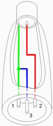
If the EUT signal ground is not itself internally grounded and is allowed to ‘float’, it can sometimes have a pretty high AC hum voltage induced in it from the power line, and you might then experience hum even on the dScope balanced input. The cure in this case is to plug the supplied XLR to phono (RCA) adaptors into the XLR input sockets. These adaptors, in addition to providing a phono input facility, automatically connect the input signal ‘cold’ leg on XLR pin 3 (hence also BNC outer) to analyzer signal ground (see the diagram to the left). Multiple grounds can create hum loops, but no ground at all is generally worse!
The dScope FFT spectrum analyzer facility is invaluable for spotting a hum problem. Just watch for those unwanted spikes at power line frequency and its harmonics. It’s also good practice to listen on the internal speaker to what you’re actually measuring!

