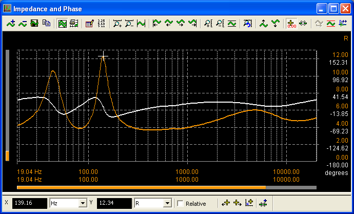
dScope Series III Scripting and automation
Loudspeaker Impedance Measurement Script
OverviewdScope Series III enables very rapid measurement of loudspeaker impedance by using a bin-centres stimulus. This stimulus has a noise like spectrum but is not random. Instead it has very distinct mathematical properties that allow analysis to be carried out with synchronous FFTs. Unlike a noise signal, the bin-centres signal requires no averaging to obtain a straight line response and can be used to measure a frequency response or, as in this case, an impedance, in a single buffer acquisition. Run repeatedly, it allows us to create an impedance response that updates every second making it possible to make changes to a design and see the results on the impedance trace in seconds. Below is a short looping recording of the impedance of an "in-ear" type earphone as it is inserted and removed from an ear-coupler.
How it works
In order to work out the impedance magnitude at any particular frequency, we need to know the current through the device and the voltage across it. dScope only measures voltage, so we use an additional known shunt resistor in series with the device we want to measure and measure the voltage across that. Since we know its resistance and the voltage across it, we can work out the current flowing through it. Since it is in series with the speaker, the current will be the same in the speaker. Then all we need to know is the voltage across the speaker which we measure directly. Using the bin-centres stimulus, we are able to do this at thousands of frequencies simultaneously by taking an FFT of the signal across the shunt resistor, and across the speaker and processing the FFT buffers to retrieve the impedance magnitude and phase.
Physical Connections
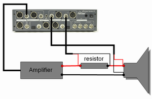
The connections required are shown in the diagram below:

As illustrated above the connections are:
- Connect dScope analogue output channel A to the power amplifier
- Connect the loudspeaker to be tested to the output of the amplifier with the shunt resistor in series.
- Connect dScope channel A analogue input across the loudspeaker terminals
- Connect dScope channel B analogue input across the shunt resistor
The choice of shunt resistor presents some trade-offs. Using a resistor of similar value to the expected impedance of the speaker is common practice when measuring speakers using computer sound cards because it gives the best signal to noise ratio. This is mainly because the voltage drop across both the resistor and the load will be similar and therefore the gain can easily be optimised on both channels. It has the side effect however of introducing problems with damping in the circuit. With dScope, since the analogue inputs auto-range independently, matching the voltages across the inputs is not as important and you will get better results using a low value resistor although very low values will give problems with noise. For measuring a typical 8Ω loudspeaker, a 0.1Ω resistor is a common choice. Note that the resistor should be non-inductive and have a high current rating. These requirements are often mutually exclusive: most high power resistors are wire wound and slightly inductive. With the low values of resistor used here, this is unlikely to present much of a problem, but for preference, a thick film resistor is a better choice. When driving large currents, the power handling and temperature coefficients may become important, although this is also minimized by using a small value resistor as the heat dissipation will be lower for any given current.
Script requirements
This application consists of two components, an automation script and a dScope configuration file. The script loads the configuration and runs the measurement. More documentation about installation is supplied with the script. The script and configuration require dScope version 1.21m or later. Running the script results in two traces (Impedance magnitude and phase) as shown below:

Noise considerations
Measurements of loudspeaker impedance are susceptible to noise from several different sources. Using a small value shunt resistor at low loudspeaker levels results in very small voltages across the shunt resistor. Any measurement of small voltages like this will be susceptible to noise. Simply turning up the amplifier level will help with the noise, but in practice it will not always be acceptable to do this as it is usually desireable to measure the loudspeaker impedance at low cone excursions. A possible remedy is to use a larger value resistor, bearing in mind the impact this will have on the damping of the circuit. Keeping cables short and using an external pre-amplifier may help, but any pre-amplifier gain will have to be accounted for in the measurement if it's different between the two channels.
Another source of noise is environmental noise. Loudspeakers are two way transducers, converting electrical energy into sound, but also converting sound back into electrical energy. Measuring the voltage across a loudspeaker in a noisy environment will show effects due to the ambient noise. Minimising the noise in the environment will minimise this effect, as will using amplifiers with low output impedances and using low value shunt resistors. Again, turning up the level will improve the situation.
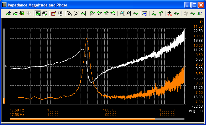
We can also reduce the effects of uncorrelated noise (noise not related to the system under test) by performing time domain averaging. Since the test signal we are using is a periodic signal that repeats once per FFT buffer length, if we make sure that we capture the signal in phase with the previous buffers we can average the captured waveforms successfully. Any random uncorrelated noise will tend to zero, reducing in level by 3dB per doubling of the number of averages. We achieve this in practice by making sure that dScope's buffer acquisition is triggered by the generator wavetable playback, then turning on time domain averaging in the FFT parameters dialogue. This obviously makes the measurement slower, but we can apply up to 128 time domain averages and make a very distinct difference to the resulting measurements. This is illustrated below where the impedance of a small drive unit from a hand-held device was measured in an office environment using a 10mV drive level:

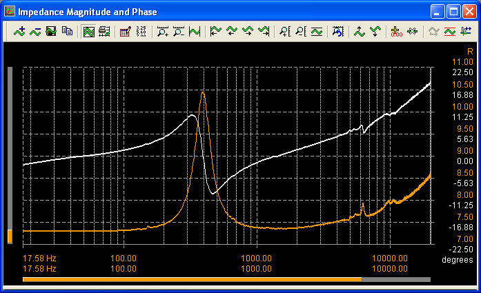
The second measurement shown below is made in identical conditions, but with 128x time domain averaging turned on.

It is also possible to select between white and pink weighted stimuli. In general, if you are having problems with electrical noise, you will get better results with a white weighted stimulus, whereas if you are attempting to measure a full range driver in an acoustically noisy environment, pink weighting may give better results.
Another technique that is helpful, and which can be used in conjunction with the selection of white or pink weighting, is to limit the frequency range of the stimulus. If you want to look simply at a port resonance for example, you could limit the stimulus to, say, 20Hz to 200Hz and increase the length of the stimulus to get better low frequency resolution. When measuring a tweeter, you can use a short stimulus that only starts at 1500Hz so as not to feed low frequencies to it which it cannot handle.
The download is a zip file containing the script, a configuration, and PDF documentation. The download is available here.

